Nitrate has a good writeup for the main flag of this challenge, which can be found here. Without repeating any details he’s already covered, let’s solve the bonus flag.
The first flag made use of the D1 and D2 digital channels - the bonus flag is hidden in the A0 analog signal.

Initial Exploration
Zooming out a little bit, I could count 43 discrete blocks of data in the signal. Odds are, each of these blocks represents a character of the flag we’re after.
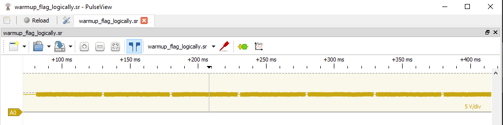
Based on the first image, though, I knew the data wasn’t homogeneous across the entirety of any given chunk. At the start of any given… - let’s just refer to these blocks of data as characters, since that’s the assumption I’m working off of - there are distinct changes in the signal, followed by a relatively very long signal of what looks to be noise. Here’s the first character to show you what I mean.
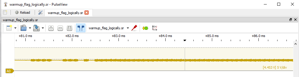
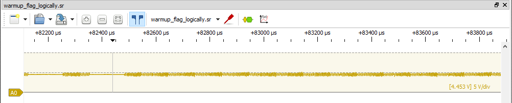
I use the word noise very intentionally. I tried to apply various analyzers to this area (I tried hard, for like 6+ hours), but even just looking at it, it is too homogeneous. You could attempt to zoom WAY in and correlate the fluctuations in voltage to 1s and 0s, but aside from a periodic increase in frequency, which is sort of visible in the image below, I couldn’t imagine any relevant data being hidden in this noise.
Instead, I chose to focus my efforts on the easily identifiable changes in signal at the start of each character. Knowing that the first flag of this challenge was encoded using UART, I thought maybe this data needed to be converted to a digital signal and decoded the same way. I tried various methods to analyze and convert this to a digital signal, but wasn’t having much luck.
Decoding the data
Eventually, I decided to try a more manual approach. I wanted to understand and identify how potential data was encoded here before I’d consider applying a transform to decode it programatically.
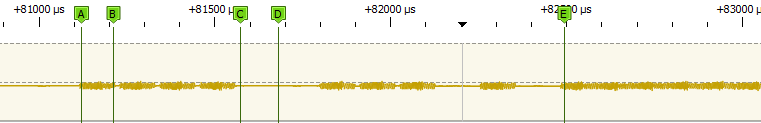
Looking at the signal in front of the first character, instead of trying to interpret high and low voltages as 1s and 0s like you would with a digital signal, it seemed a better approach to instead interpret a given period of roughly 5µs as being either “on” or “off”, i.e., 1s or 0s.
You can see what I mean in the following image, where labels A-B represent a 1, labels C-D represent a 0, and label E is where the noise starts for the remainder of the signal representing a character.
From here, I stepped across the first couple characters and mapped out my interpretations of 1s and 0s to see if anything stood out.
| Character | Bits |
|---|---|
| 1 | 111100111010 |
| 2 | 111110011010 |
| 3 | 111011111010 |
| 4 | 111000111010 |
| 5 | 111010010110 |
One thing that stands out to me is that every character starts with 111, and ends with 10. I quickly scrolled through a few more characters to confirm that this pattern continued.
I think it’s a safe to assume that since there is no change in the data, there is no information to be gleaned from looking at these particular bits. They are likely just used as a sort of STOP and START signal for the encompassing bits. That leaves us with the following information:
| Character | Bits |
|---|---|
| 1 | 1001110 |
| 2 | 1100110 |
| 3 | 0111110 |
| 4 | 0001110 |
| 5 | 0100101 |
I’m getting a bit excited now, because we’re left with 7 bits of information - the exact number of bits required to represent ASCII text! There’s a problem though… these bits, in their current form, don’t all correspond to printable characters.
| Character | Bits | ASCII |
|---|---|---|
| 1 | 1001110 | N |
| 2 | 1100110 | f |
| 3 | 0111110 | > |
| 4 | 0001110 | SO |
| 5 | 0100101 | % |
The first flag in this challenge, as per the challenge statement, followed the form “FLAG-{ }”. Maybe there’s a way to correlate these first characters with “FLAG-“.
The idea is to figure out some sort of transform or encoding that is taking the current determined bits from my assumed characters and turning them into the bits representing the characters in the string “FLAG-“.
| Target | Bits | Character | Bits |
|---|---|---|---|
| F | 1000110 | 1 | 1001110 |
| L | 1001100 | 2 | 1100110 |
| A | 1000001 | 3 | 0111110 |
| G | 1000111 | 4 | 0001110 |
| - | 0101101 | 5 | 0100101 |
Notice character 3, and compare it to the bits of ASCII A. They’re both palindromes, but the bits are flipped. Let’s follow this thread and flip the bits of our characters and see if they look better.
| Target | Bits | Character | Bits | ASCII |
|---|---|---|---|---|
| F | 1000110 | 1 | 0110001 | 1 |
| L | 1001100 | 2 | 0011001 | DC3 |
| A | 1000001 | 3 | 1000001 | A |
| G | 1000111 | 4 | 1110001 | q |
| - | 0101101 | 5 | 1011010 | Z |
Still no luck on the ASCII, but the pattern between the target and current bits almost jumps out. The bits are now like a mirror image… The character bits just need to be reversed to match!
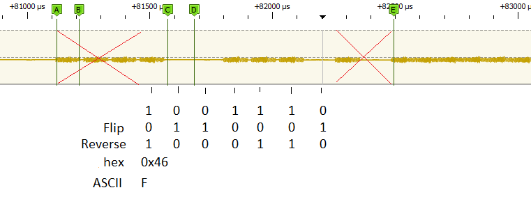
Here’s the steps required shown on the first character block of data, to decode the signal to the ASCII character F.
Stepping through the rest of the data and using some excel magic, the flag can be deciphered.
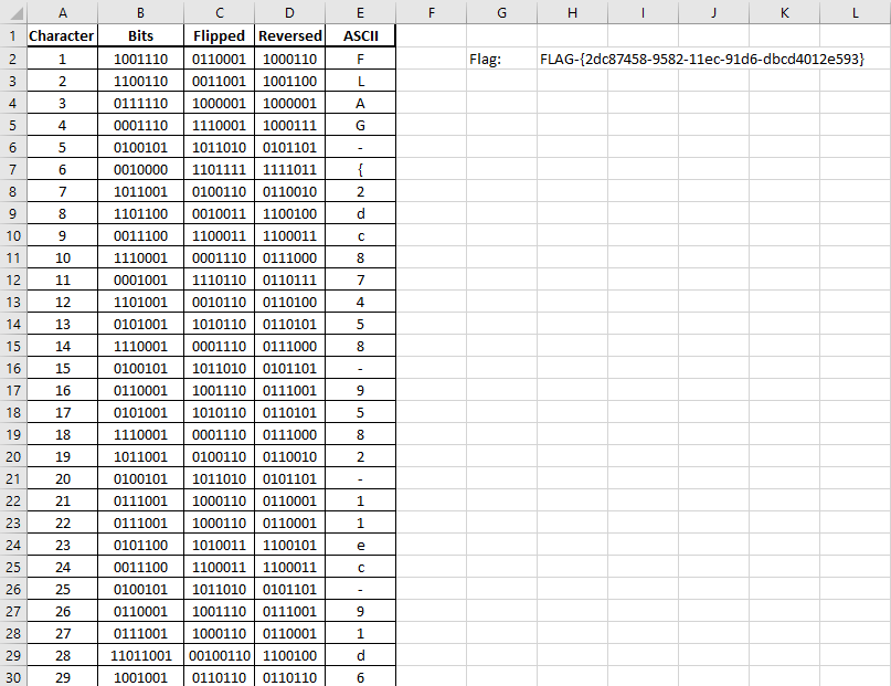
I input the data in Column B.
Column C uses the following formula to flip the bits:
=SUBSTITUTE(SUBSTITUTE(SUBSTITUTE(B2,1,2),0,1),2,0)
Column D uses the following formula to reverse the bits:
=TEXTJOIN("",1,MID(C2,{7,6,5,4,3,2,1},1))
Finally, Column E uses this formula to convert the binary to an ASCII character:
=CHAR(BIN2DEC(D2))
The final flag: FLAG-{2dc87458-9582-11ec-91d6-dbcd4012e593}.
You can download the excel file here.
Now, this encoding very probably corresponds to some known scheme. If I had to guess, it’s likely reverse encoded something with multiple stop bits, where a lack of signal is 1 and a positive signal is 0. This corresponds to the need to flip and reverse the bits in my manual solution.
I could explore further and try to get some software to analyze and decode it properly, butttt it only took 20 minutes to throw it into excel and solve it that way. I’m a big fan of simple solutions, whenever possible. :)